Sunday, August 4, 2013

The arm

The arm assembly

This part was done well before the bicep assembly which I have already done a blog post about but I just didn't want to risk being accused of being organized. All told the forearm and hand assembly was quite an adventure and actually continues to be interesting. The main reason for all that is that this was the first part that I tried to print and to assemble and as such has been loaded with errors that I had to correct. 

This picture show the arm, wrist and hand in the process of connecting the strings. Actually the second time I did the strings. The first time was with some waxed cord that I found at the hardware store before I had ordered the 200 lb test fishing line. It didn't work very well, hence the change. The strings lay flat across the wrist like that because I put a piece of double sided tape there in order to keep the strings in order as I pulled them in. Paper plates are an important part of my accessories. I use them for almost everything.


A detail shot of the forearm with the servo cable for the wrist servo.


This is a shot of the arm and hand when I was partway through the process of attaching the strings to the servos and the ugly knots that I was making. I was making tighter and tighter knots to adjust for slack in the strings. What I didm't realize at the time was that I had not paid enough attention to the routing of the strings. I made two important mistakes: I had gotten the strings for different fingers wrapped around those for other fingers and I had not paid enough attention to getting the pull strings on top of all possible passageways and the return strings on the bottom. The combination of these two things made trying to get proper tension in all the strings a real mess and trying to get all the fingers to pull and return mostly impossible. A bit later in the process I pulled and re-strung all the strings getting them all straightened away. I actually untied all those ugly knots using a magnifying glass and tweezers. Like I said, doing this process was a real adventure.

By the way, I had the servos connected to a Raspberry Pi by way of an Adafruit 16 servos board. The Pi that I was using was actually the control for a wheeled robot that I was playing with.


Here is an overhead shot.


A shot with all the strings attached. If you look closely you can see the confusion of strings as they enter the wrist. The problem may not be obvious unless you have tried to do the strings once. Also, you can see that three of the fingertips are pulled up. This is evidence of the problems with string tension due to tangling.


A shot of the arm during testing. The small thing with 6.2 showing is a step down voltage regulator running on the battery pack of 8 cells giving 12 volts. The index finger is flexed.


The arm assembled with Joe Walsh on the tube. At this point in the process I had already restrung all the fingers and tested the whole arm. As I discovered later there were more errors during this process that would add to my later enjoyment.


I may not sound like it at times but I am really enjoying this process. 

Next the arm, shoulder and torso assembly. And the other arm that is keeping the printer warm in my absence.


Thursday, July 25, 2013

New servo holder - better flex

After printing the newest servo holder and assembling, here is a picture. It looks better than the last version.


Morris

Wednesday, July 24, 2013

Prosthetic finger version 3 assembly

This is another version of the finger and new actuators. The actuators were redone because they were printing thicker that was intended. Here is the same sequence of pictures, extended, flexed and extended. The cutters are to hold down the servo holder.


The extend position looks good but the flex position is still short of ideal. After peering down inside for a while I found that the #1 actuator was hitting on the servo holder in the flex position causing the rotation to stop short of the end. Here are two pictures showing the flex position with the actuator #1 lower pin in place and with the lower pin pulled out.


Either some of the servo case has to go or the actuator needs a redo.

Morris

Prosthetic finger version 2 assembly and success

I printed the new versions of the finger and the actuators. There were some small problems with three parts of the fingers and the actuators printed a bit thicker that the previous ones.

This picture is of the new pieces.


I think they are much more attractive in purple.

This picture is of the bottoms of the three parts that have a first layer problem.


This one is of the assembled finger in the extended position.


... and the flexed position ...


... and the extended position once again.


Each of the flex/extend positions were done by moving the part connected to the servo base only and no adjustment of the other pieces was done. I would call that success. There is a newer version that I have not yet printed that should take care of the actuator issues and the finger layer 1 problem.

Also, I have a working servo holder/worm gear assembly that has to be mated to the 'final' version of the finger.

More to come.

Morris

Saturday, July 20, 2013

Finger assembly #4 and other stuff

Assembly test #4

Here is the info about the latest assembly of the prosthetic finger.

I printed the two new parts and they are a fraction shorter. I assembled the pieces and the finger comes closer to working but not quite.

Picture of the pieces before assembly. You can just see the little filament plug that I glued into the tip to connect the actuator to.


With the actuator on the pin.


The finger together but without the various filament pegs.


And the finger with the pegs.


Now, the flex tests. This picture is when I rotated the gear to check the flex. The tip is still in the start position.


And this one is the result if I turn the gear quickly. The momentum of the other joints flexing causes the tip to flex also. When the finger is flexed as in this picture or the prior picture, the tip joint can be moved from the straight original position to the flexed position and back but the actuator does not have enough 'pull' to keep it flexed.

Prosthetic finger servo and worm gear

While I have been working on assembling the finger I was working on getting the worm gear and servo together and ready to run the finger. I got the worm gear to run freely in the servo holder and got the worm gear mounted to the servo. I have not yet received the Corona servos for this so I am using a micro servo that I had laying around. In order to make things fit I made a 7 mm diameter 2 mm thick spacer and then glued the worm gear, space and cut down servo horn together. Tomorrow will be making the assembled bits flex the finger, hopefully without breaking any of the delicate little bits. 

Here's some pictures.


Torso mostly together

In my quest to eventually get a whole InMoov together I have gotten one shoulder and most of the torso and some odd left shoulder parts printed and together. I have a torso mount and an old broomstick connected to the end of my table with the torso mounted. I imagine my InMoov looking over to check out what I am doing occasionally.

The 3d printer difficulties have been greatly reduced lately except for a broken X axis pulley and a randomly failing extruder that turned out to be bad bearings and a pulley slipping on its shaft.

Here's a picture of the torso. You need to supply the missing head and arms in your imagination.


Well, I can see the head and arms.

Morris

Friday, July 19, 2013

Prosthetic assembly #3

After dealing with extruder problems I managed to print the new finger piece to try to get the finger tip to flex. On looking at the printed part I could immediately see that the new hole was so close to the edge that there was really not enough plastic to give the end any strength so I had to add some plastic around the hole and on the edge. The red part is the added plastic. 

The next two pictures show the new part in place with the filament pins and flexed. The addition of the new hole and pin essentially locks the tip into a non-flexed position.


The next picture shows the finger in flexed position with the new pin removed and the finger tip part manually flexed. It appears that the finger tip would need to pivot around the new hole location and the relative location of the actuator end would have to shorten in relation to that pivot location.


The next two pictures are taken from the other side in order to show the location of all the pins.


I tried to fit together the part with the new hole and the other parts in as many ways as I could but the way it is shown here was the only one that allowed all the holes to match that I could find.

Morris

Wednesday, July 17, 2013

Prosthetic assembly test #2

After Gael told me I had the first actuator upside down the assembly went a lot better. Here is a picture of it together but with filament pins still sticking out. I haven't done the servo assembly part yet.


And a picture with the finger flexed. The end joint does not flex yet. There doesn't seem to be a mechanism for making that joint move. I can see that there is a hole in the end piece without a way to insert a pin and no matching hold in an actuator. I may still have an assembly error. Important part here is that rotating the gear part flexes the finger.


Here is a shot from underneath to show where I used my exacto knife a bit to make clearance for the gear to rotate.


Morris

Tuesday, July 16, 2013

Prosthetic assembly test

I got a little time to test assemble a bit and I found a couple of problems right away. This is with the center servo holder part, the first actuator and the first finger piece held together with a piece of filament. The end of the actuator does not look as curved up as in the assembly drawings. I don't know if that is an actual problem or not. Also, the shape of the top of the actuator will not allow the next piece of the finger to fit together correctly. It will be easier to see in a later picture.


This picture includes the next piece of the finger and this is as well as the pieces will fit together. 


This one shows down into the second finger piece and shows the conflict with the actuator and the finger piece.


This picture shows the under side with the three pieces assembled and shows the conflict between the gear teeth and the under side of the servo holder. The interference here will not allow the gear piece to move at all.


I hope that helps some. 

I will work tomorrow on attaching the servo to the worm gear and getting the worm gear to rotate well in the holder.

Morris

Prosthetic finger first print

My first attempt at printing the prosthetic finger

Here are some pictures and printing data about the prosthetic finger from Gael. One of the areas of 3d printing that has been a struggle is printing of small parts and these models really push what I have learned to do so far. The following are photos of the parts with comments about what settings I used. The camera I used, except for the last picture, is a small point and shoot and does not focus as close as I needed. For the last picture I dug out my Canon SLR. I will do some better pictures of the other parts later on.


Actuators. Printed at 20mm speed, .2 mm layer height, .3 first layer and solid infill.


Servo holder. Printed at 40mm speed, .3 mm layer height, .3 first layer and solid infill.


Finger. Printed at 20mm speed, .3 layer height, .3 first layer and solid infill.


Worm halves. Printed at 20mm speed, .2 layer height, .3 first layer and solid infill.

A little bit of explanation goes along with this picture. For the moment I have given up on printing things like worm gears in the vertical orientation due to problems with overhangs and support. I have not yet been able to print these without having to do an excessive about of carving and sanding. My current experiments in this area are to cut the piece in half vertically and then rotate each half to be flat. Each piece is then printed and the pieces glued back together. In the following picture the red line down the side of the gear can be seen. I used some goop made from acetone and red filament as glue. 


Worm. The glued together worm gear.

I will be starting to assemble the finger later today but I don't yet have the servos in hand. The size of the worm gear makes me wonder about how to attach it to a servo. I suspect I will have to go in search of some very tiny screws.

Sunday, July 7, 2013

Back from vacation - Start on bicep

Starting on the bicep printing and assembly

I was actually expecting to start on the assembly and testing of the hand and forearm but the servos I had ordered to be delivered as soon as I got back from vacation did not arrive. I ordered six MG996R servos from Hobby King but they never shipped and it appears that they were terminally out of stock. So, as soon as I got home I ordered another set of six by way of Amazon. They shipped almost immediately, albeit from Germany, but they got here in about 7 days.

In the mean time I decided to proceed with printing and starting to assemble the bicep and I immediately sank into a new session of discovering how many ways a newbie with 3d printing and a newly assembled 3d printer can use up rolls of filament. One of the really important concepts I began to understand is that almost every piece to be printed has a seemingly new set of potential screw ups embedded. Just for fun here is a list of some of the things that went wrong:

3d printing boo-boos

I discovered that I had been trying to print using a .35 nozzle with slicer set to a .5 nozzle. One of the myriad settings that I missed. This was causing real bad stringing and clumping.

I really did not understand about setting the starting Z height correctly primarily because trying to set this accurately with the Z stop switch holder that is standard on a Prusa is a nightmare. I finally sorta set the height somewhere and the used the Z offset up and down to find something that worked. This was not a very effective way to operate. Later on after another week or so I build a screw adjustable Z height bracket and used a better switch holder from Thingiverse and then learned to actually get the four corners of the bed to be level. I ended up with a good working height to be about 4 sheets of laser printer paper.

I did not grasp the importance of the belt tension ( y belt this time around ) and was seeing some prints that looked like pictures I saw online of y belt tension too loose. Tightened up the y belt and printing improved a bit. For some reason, checking the x belt didn't occur to me. A while later I made a little adjustable belt tensioner for the y belt. That really resolved issues with keeping that belt tight.

I was having problems with the sides of my prints with ripples. After poking around on line I discovered that this is called 'Z wobble' and can be identified by holding something printed up beside one of the z screw rods to see if the ripple pattern matched the threads. The pattern matched. I set about trying to figure out what was wrong and how to resolve it. I tried a variety of things and finally decided to replace the z threaded rods. That resolved most of the issue but there is still a slight detectable wobble pattern. I'll get back to fixing that when I get some time.

In the process of getting printed pieces to stick to the bed and not warp I have gone through a bit of trying different forms of black magic. Seems like black magic anyway. This period started with me using Kapton tape on glass with a coating of abs/acetone on the tape. I went through phases of this working very well and then not working at all. I tried varying the hot end and bed temperatures, printing directly on the glass, printing on the glass with different thicknesses of hair spray and finally back to Kapton with abs/acetone. What I did not realize at the time was that a lot of the problems with sticking were related to Z height and bed leveling. I now print on glass with Kapton and a fairly light coating of the abs/acetone mix. Another thing I now do is to spray the clean glass with windex before applying the Kapton the push the bubbles out while the Windex is still wet. Then when the Kapton is dry I print on it. Works to a treat.

One of the problems I am still having is how to get a good print of things like to worm gears for the bicep and shoulder. If I don't use support I get good tops and saggy underneaths that make a really unusable print. If I use support I get so much crap stuck to the undersides and edges of the gear faces that I have to whittle till my fingers hurt. I have seen people say to use a fan to cool the plastic quicker but I haven't seen any examples that are close enough to my combination of equipment and models.

Finally, the x axis pulley gave up. It cracked and lost a tooth. The indications from that were so obvious that I couldn't miss them. Having the belt skip a tooth every rotation gives a rather distinctive pattern.

The bicep

Hope all of that wasn't too boring. Getting up to speed with the printing and assembly of InMoov is a fascinating process and I can't help talking about the process.

Anyway, I went through the process of printing out all the bicep pieces for the right arm (some were printed multiple times) and started the process of assembly. Since I was following the bicep assembly help section the first thing up was to modify a couple of hs-805bb servos for continuous rotation and for external potentiometer. A problem I ran into with the procedure is with pulling out the motor and small pc board. No amount of coercion would allow me to pop out the motor and board. I later found that the motor was securely glued in place. What I did was to unsolder the motor from the pc board and solder it back when I was finished. In order to unsolder the motor there are three soldered points to undo. In the following picture they are the two points on either side of the bottom of the motor and the point on the right side and a little above the right motor point. The third point is a ground connection. You will need a solder remover tool to do this de-soldering.


When I did the first servo I did not realize that the third point (ground) was connected to the motor and I broke the wire loos from the motor. To reassemble the servo I had to clean out the solder, solder a wire to the frame of the motor and then solder it back to the pc board with the other two points. Here is a picture of the bottom of the servo with the wire soldered to the motor and before the replacement of the pc board.


The rest of the procedure is essentially the same except that it is not necessary to remove all the gears, only part of them.

Bicep rotation gear assembly

The most troublesome part of assembling the bicep was the arm rotation assembly. Between the problems with trying to get a decent print of the worm gear and the really tight tolerances for the whole assembly I spent many hours fitting and whittling and fitting and whittling, etc. It was and actually still is a real challenge getting this part to work correctly.

Once I got an assembly that would operate sort of smoothly I decided to spin it for a while using my electric drill. I build this little attachment using the end of a broken worm gear and a bolt.


 I then attached that fixture to the end of the worm gear.


Then the assembly was assembled. I did put the cover on before running.


and then I chucked it up in the drill and ran it for a while going in both directions. I then opened it, blew out the dust and checked that the works still worked.


The bicep assembly

After messing with the arm rotation assembly I did the rest of the bicep assembly. Most of this was reasonably straightforward work. The instructions were easy to follow as long as I followed them. Here is a partial assembly with the attachment piece for the forearm. Actually if you look closely this is assembled incorrectly. The bicep assembly is mounted to the rotation plate upside down. Part of the instructions that I did not pay close attention to was to test the assembly before glueing it together. This one went in the trash and another was printed and assembled.


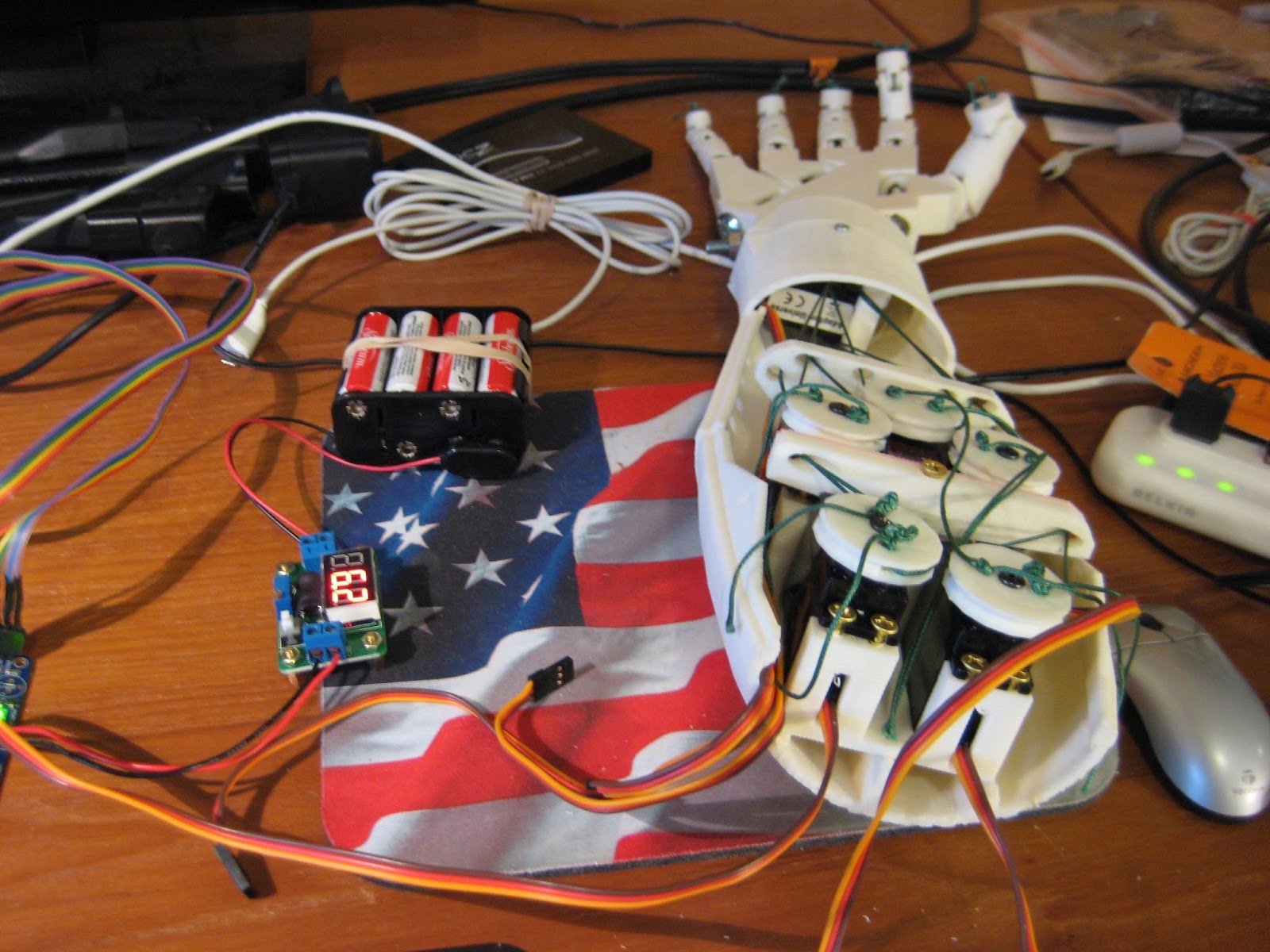
Here is assembled arm before adding the bicep skin and just before connecting the servos to the computer to do some more testing. On the left edge of the picture the Adafruit servo board and Raspberry Pi are just visible. Also, the Eagles on the tube.


That's about it for the bicep. Next blog post will be about the finishing of the hand and forearm. I have printed all the parts for the torso and had finished about half the shoulder parts before my x pulley broke  (see above if you haven't already). I am really excited about maybe getting a robot together soon. I need all the friends I can find (or print).

Later